Handling magnetised magnets may cause major problems for transport and assembly. There is risk of injury due to high magnetic forces they may pick up metal fragments and may hard to store in their assembly location.
In contrast it is easy to handle unmagnetised magnets and assemblies during transport and storage. These can be magnetised on site during the production process.
Main reasons for the magnetisation on site of magnet assemblies are:
- Easier handling and packaging
- Reduction of contamination (e.g. iron, steel fragments and dust )
- Reduced risk of injury
- In some magnet system the magnetic layout requires iron return paths for the stability of the magnets eg AlNiCo magnets.
- Higher yield on increasingly valuable parts
The basics of the magnetising process
A permanent magnet is magnetised by application of a strong external magnetic field applied by the magnetiser through the magnetiser coil fixture.
In classical electromagnetism, magnetisation is the vector field that expresses the density of permanent or induced magnetic dipole moments in a magnetic material. The origin of the magnetic moments responsible for magnetisation can be either microscopic electric currents resulting from the motion of electrons in atoms, or the spin of the electrons or the nuclei. Net magnetisation results from the response of a material to an external magnetic field. https://en.wikipedia.org/wiki/Magnetization
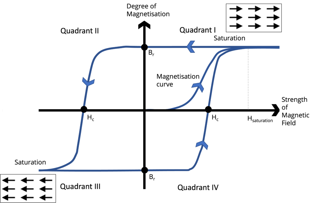
Simply the magnetic field forces the spin of the electron to be align to the field applied. As the external field increases the magnet become increasingly magnetised. Once the external field strength is greater than field the magnet assembly can hold the magnet is fully saturated.
In case of permanent magnets this sticks and the magnet remains magnetised when the applied external field goes back to zero. The magnet will stay at the positive remanence point (Br) unless exposed to a strong enough demagnetisation field.
In the second quadrant of the hysteresis loop the applied magnetic field is in opposition to the sample magnetisation, this quadrant is referred to as the demagnetisation curve, it is of special interest because this is where most magnetic machines operate.
Hirsts approach
All Hirst magnetising systems contain capacitors which are charged via a low voltage charging system to a high voltage (800V, 1000V or 3,000 volts) and discharged through the magnetising fixtures or coils. The design of the magnetising coil is key to ensuring the right magnetising result and this is accomplished as part of a detailed design process – see our magnetic design process web page.
In order to magnetise an item it is necessary to expose it to a sufficiently strong magnetic field. The magnetic field is generated by passing a large current through a special coil of wire known as a fixture.
Each magnet is created when a suitable piece of material is placed in the centre of the wire coil and subjected to a strong magnetic field generated within the fixture.
The fixture is often designed specifically for the application ensuring it generates the required field over the specific area/volume of the magnet. The fixture needs to be protected against damage caused by high voltages and currents, excess temperatures and mechanical stresses generated during magnetising.
Many types of magnetising pattern can be produced, each one being associated with a specific industry application – see our custom fixture webpage for examples.
Capacitive dischage systems
Capacitive discharge magnetisers are used where the required magnetising current is too high to be achieved using direct power from the mains supply. Depending on the exact requirements of the geometry to be magnetised, the material type and the fixture design, this current is often in the range 5000-10000A but can also be much higher.
A capacitive discharge magnetiser, charges up an internal capacitor bank to a required voltage level over a short period of time. This stored energy is then discharged into the magnetising fixture (in a much shorter period of time), in a controlled manner, producing the large required currents and hence magnetising field strength.
Hirst incorporate microprocessor technology in their magnetisers to safely manage the charging and discharging of the machine during the magnetising operation making it very safe to use. Hirst have an extensive range of products for all applications – see our magnetiser webpage for a full list.
Magnetiser energy
The energy required to saturate a magnet or magnet assembly and therefore the size of the capacitor bank is calculated from a combination of the required field strength to magnetise the magnet (magnetic material properties) combined with the magnetic assembly geometry and dimensions. Capacitor banks with stored energy from 100J to over 400kJ are available, with operational voltages from 800-3000V. For more details see our magnetiser webpage.